Friday 31 October 2008

November 2007


Scuttle and Pedal Box


With the engine in place and some of the minor problems fixed it was now time to look at fixing the scuttle. My intension was to make up the scuttle with the firewall in place along with the dash but i wanted to be able to remove the dash to allow access for me to make the wiring loom and secure the fuseboxes.


It was a fairly tricky job. Both the scuttle and the dash come flat and need to be bent to shape. After folding the tabs on the firewall it was a case of lining up the scuttle to the fire wall, mark, drill and screw. Once the first screw was in i repeated this right round until the basic shape had been formed. I then mocked up the scuttle on the chassis to get the positioning right. There are quite a few bends on the Zero dash and it come in two parts. The first has the teeth around the edge and none of the middle section and these need to be folded to secure to the scuttle. The idea is the first part of the dash secures to the scuttle and the second effectively sits over the first part and rivets on. Once all was secured in place i unscrewed the dash section and removed it to allow easy access to the loom. Once i put the first dash section in it would be a while before the dash facia was put on which i'll write about in this blog.
Finally the pedal box. This was very straight forward. Bent the ally to shape, and secured in place.

Thursday 23 October 2008

27th October 2007


Problems discovered after dry fit!!


I borrowed an engine hoist from one of the club members who was very kind in lending it to me (snapperpaul) and lowered the engine in. After the initial struggle of getting the engine to slide onto the gearbox shaft (which it finally did!!) a number of 'issues' presented themselves.


1) When i came to put the engine mounts on i bolted them to the holes on the block as instructed by GBS and ffrom personal research on the t'internet but the £60 mounts i had bought from GBS were wrong. Firstly they got the angles wrong and secondly the lengths wrong. So the net result was if the engine was seated it would have leaned to the left, but, the main inssue was that as they were the wrong angles if i tightened the mounts to the block coupled with them being to long meant they missed the plates on the chassis to sit on adn were hanging out the sides of the car!!! I have a friend who is a steel fabricator so i took them to him with fresh measurements and had the cut and re-welded!


2) The oil filter. This caused me a lot of headaches and trips to the motor shop down the road. On the silvertop the oil filter is angled down. Unfortunatley the steering column runs right across the face of where the oil filter screws to. I had to find an oil filter 55mm deep!! After searching high and low i found one from a renault 5 but this was just a tad to long at 57mm!!! I called Burton Engineering and bought a remote oil filter adaptor (49mm!!) and the appropriate hosing!! Mounted the new filter adaptor to the chassis and screwed on the new adaptor to the block.

With the new remote oil filter adaptor on i needed to prime the oil pump. This needs to be done on new engines and was recommended as mine had been sitting a long time. Another club member came to aid here in the form of Longboarder (Nigel, who has helped me massively!!!! especially with the wiring!! having never wired before and with his guidence managed to make my own loom!!) and said i needed to wind the crank anti-clockwise to the pump sucks oil in from the filter and primes the pump!! A little tricky when the oil filter has a non return diaphram!! So i grabbed a tin of soup, put a single hole in the bottom, drained the soup (into the saucepan of course!! excellent lunch that day!) then drilled 8 10mm holes around the central hole and made the central hole to about 12mm. Then cut a square hole on the side and screwed the tin can onto the oil filer plate. Filled with oil and turned the crank until it had sucked all the oil in!! Job done. Oil pump primed!!

Finally, out of some thin ally i cut a new sandwich plate to got between the engine and gearbox and the existing zetec plate did not fit and cover all the gaps.


27th October 2007


Time to dry fit the engine!!


I bought a 2.0l zetec (silvertop, as i didnt want to have to run a cat with my exhaust set-up) about a month before picking up the kit. As the zetec came out of a auto Mondeo there were a couple of things i needed/wanted to do to the engine before i could fit it. Firstly i contacted a company called Dunnell Engines who provided me with a shortened sump and a lightened & balanced flywheel adn clutch to suit. I also needed to put a spigot bearing into where the input shaft of my type 9 g'box goes as the engine originally took an auto box. Next was to change the water pump to an escort 1.8 pump as the pump spins in the opposite direction to the Mondeo pump and i could then get rid of the pulley wheels and just have the cam pulleys, crank pulley and alternator pulley i a triangular formation. Finally i had to change the VR sensor to read the 36-1 teeth on the flywheel for the Omex ECU which was a fairly straight forward task. Once these jobs were done i put a new head gasket on and gave the engine a lick of paint!! (rocker cover was done later!!!!)

Monday 20 October 2008

24th October 2007


'You gotta roll with it....................'


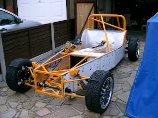
Finally i have the car as a rolling chassis!!! Yay!! The 2.4 quickrack and steering column are all also in place and i've started with the wiring. I'm trying to hide and much of the wiring as possible and am running a lot of it in the chassis tubes themselves.


Friday 17 October 2008

24th October 2007


I wish........................


Once the exterior side panels were on this meant i could then fit the front wishbones. Fresh out of the paint oven in the same orange as the chassis i repeated what i had done on the rear w'bones and pressed the poly bushes in, inserted the tubular inserts into the bushes (trimming each one to be flush with the width of the bushes) and then 'wrestled' the w'bones onto the chassis and 'persuading' them to line up!! The only difference this time was knowing that i was working around a fresh new ally panel! One slip and........................!


Once on and secured i then had to put on the upper and lower ball joints. These were supplied by GBS with the w'bones. The upper ball joint effectively screwed into the w'bone and was the camber ajustment. I bought on eBay a pair of brand new front hubs for about £70. The cycle wings GBS provide are modified and welded to the stub axles. So i quickly put the stub axle and hub together and mounted onto the lower ball joint. I nutted up the upper ball joint but not overly tight as i knew once the car was complete i would need to undo this again to finalise the camber setting.


I bought a set of Gaz coilovers from Dampertech (who were about £40 cheaper than what GBS were supplying for the same product) and fitted these on. This was a very quick job just ensuring that the front pair were set up the same and the rear pair were set up the same. I would need to experiement with final set-ups when the car was done. Finally i just mounted the wheels and tyres i had bought on eBay. Brand new set of 16" TSW Catalunya's, brand new tyres - £399!! I great bargain i though!!


15th October 2007


More Panels!.....................
The next of the panels to go on was the transmission tunnel side panels. I purposefully left the top tunnel panel off until the last moments of the build to allow access to the prop, wiring and brake & fuel lines and also to change the gearshift to a quickshift which i decided to do after the g'box was in!

Shortly after the trans panels i fitted the rear interior side panels and the exterior side panels. All of the panels come pretty much platpack!! All are cut to size (and may require additional trimming and all will need filing on the edges) but it is up to you to bend and form the panels into shape. There are some that have some 90 degree bends which are pre-bent by GBS but panels like the scuttle and rear panel need you to create the curves!!! Also a lot of the panels have inch wide 'teeth' that require you to bend these to 90 degrees. Make sure these are bend equally to create a flat surface. Any teeth folded to much or not enough will stick out like a sore thumb and affect the mounting of the panel.

The panels in the pics all went on without any real hassles. Just the odd trim job and file and a whole lotta rivets!!


Thursday 16 October 2008

12th October 2007


G'box and Rear Panel................


Next up was getting the gearbox in place along with the prop. All fairly straight forward. The metal edges of the rubber g'box mount needed trimming to allow it to sit flush in/on the mount welded on the chassis. Then had to drill 4 holes through the welded plate and the metal surround on the rubber mount to enable all to be bolted together!! Once the g'box was put in place and the prop attached all bolted together!

I made, what i think now was a very wise decision to buy a compressor. It added about £150 to the budget which was a pain, but it meant i could run an air riveter which saved me soooooooooo much time!! I've in excess of 1000 rivets and wore the first riveter out!! But also meant i could use the grinder and sanders.

This leads me onto the first of the ally panels. The rear seat back panel. I had some metal drill bits and started to drill the 4mm holes, but, the very first hole and the drill bits were useless. Each bit blunted after one hole and each hole took forever!! My intial thought was 'this sucks' my second was 'im never going to have this done by summer 08'!! I went to a local nuts'n'bolts factors and bought four 4mm Doorma bits and with these its like drilling through cheese!! Used 3 and have 1 left!


Wednesday 15 October 2008

11th October 2007


Rear Hubs and Master Cylinder........
The next task in hand was to fit the rear hub carriers and the rear hubs themselves and the driveshafts. I painted these and and pressed new wheel bearings into the hubs. I was opting for XR4x4 discs all round and GBS provide (which i also think they provide if you have drums but not sure how they fit with drums) about 4x 1-2mm steel spacers that sit behind, and is sandwiched between the hub carrier and the hub carrier 'carrier' that is made and welded by GBS. This welded piece from GBS has the lower w'bone attach to the bottom and the upper w'bone to the top (see pic!!!!!!!). The hub carrier then sits on the face of this with 4 of the 8 spacers in between. Once the driveshafts are in place the hub slides on and is nutted up. Regarding the 8 spacers, the pre-drilled holes may need opening up very slightly to enable all the holes to align and the bolts to go through freely.

Next was on to the master cylinder!! Fairly straight forward. Bolt on and attach the brake lines. But, make sure all the pipes are flared properly before connecting to the master cylinder. Frustratingly i had no end of problems for some reason with leaks from the pipes not sealing correctly into the master cylinder!! Turns out though my master cylinder was knackered and i had to buy a new one!! Finally, if you are running discs on the rear i had problems when the calipers and brake lines were in place with bleeding the brakes. I bled the brakes every night for a week using different methods and could not get pressure. Turns out the rear calipers on the donor are mounted at the top and not on the side as on the zero. Because of this the little 'resevoir' in the caliper itself trapped air!! So i unbolted the caliper, moved it round and hey presto all bled ok!!


Tuesday 14 October 2008

9th October 2007


Rear W'bones and Brake Lines.......

My brother who is a panel beater and sprayer by trade kindly painted my front and rear wishbones (front orange and rear black) and so i fitted the rear w'bones, which was a task for various reasons. Firstly have to press 32 poly bushes into the rear w'bones and all where a tad to big for the tubes they were pressed into and made each one i nightmare to get in. Secondly once the bushes were in getting the w'bones to bolt into their mounts on the chassis meant having to spread the w'bone apart very slightly to slot them in!! To add to this there were 16 tubular sleeves that slid into the bushes that were all about 1mm to long and therefore would not slide into the mounts on the chassis!! Out with the grinder and finally after alot of huffing and puffing the w'bones lined up and i got the bolts through!!


After that i secured the fuel line and brake lines in the transmission tunnel. I thought it made sense to do this now as getting the drill in the trans tunnel might prove a pain when the panels were on or worse i might scratch them!! To reduce vibration and possible damage to the brake lines i bought some 4mm i.d. silicon tubing and thread the brake lines through this and secured with 'p'-clips every 5-6 inches.


8th October 2007


Painted Chassis and Rear Diff.......
Here's the chassis all painted and the lsd diff fitted. All ready now to start adding parts!! Small problem with fitting the diff being the top bolt holes were completely out of alignment!! So the diff (which was pretty heavy and awkward to get in!) needed to be pulled out again for the holes to be widened. Once this was done all bolted up nicely!!


6th October 2007


Chassis Pick Up.........

Picked up the Zero chassis and various parts that managed to fill a Mercedes Sprinter Van floor to ceiling!!

Spent the afternoon (after driving 230 miles) grinding down the welds, preping the chassis for paint the following day and adding my additional rollbar that runs from the rollbar to the passenger footwell.


Hello and Welcome

Hello and Welcome!!

This build diary/blog is still very much under contruction!! So keep popping by for updates and pictures of my RH Zero build!!

Scott